Chassis Dynamometer
섀시 동력계
Integrated Testing Solution
Patent No.: 10-1342905: Test Dynamometer Bench Device for Small Electric Vehicles
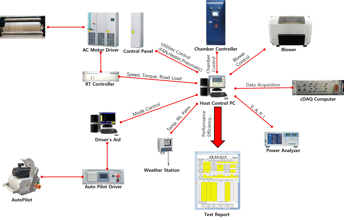
We provide integrated test solutions based on powerful networking solutions. We continuously develop to meet diverse customer testing requirements, and we develop and supply chassis dynamometers specialized for testing electric bicycles, electric two-wheelers, and electric four-wheelers. The DNB chassis dynamometer features maximized user convenience, enabling Test Then Report.
Overview
제품개요
System Configuration Diagram
Models
모델리스트
| Model Name | Capacity | Features |
|---|---|---|
| ET CDMAC-30S | 30kW | 2WD, Bicycle, Electric two-wheeler |
| ET CDMAC-70S | 70kW | 2WD, Electric two-wheeler |
| ET CDMAC-110S | 110kW | 2WD, Ultra-compact electric vehicle |
| ET CDMAC-110D | 113kW x 2 | 4WD, Ultra-compact electric vehicle |
Specifications
주요사양
Software and Control Systems
Software and Control System
- Dynamometer Operation Program
- Maintenance Test Program
- Report Program
- Parameter Set-up Program
- Calibration Program
Test Mode
Test Function
- Single-charge driving range test
- Gradeability Test
- Maximum Gradeability Test
- Top Speed Test
- Acceleration Performance Test
- Constant-speed test
- Constant Load Test
- Coast-down Test
- Parasitic Loss Test, etc

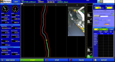
Driver Assistance System
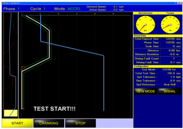
Driver's Aid
- User convenience is emphasized, making it easy to drive
- The driving caution error indicator features display lines for vehicle speed and time to comply with KS standards
- Grade display is available (First in Korea)
- User mode creation is possible (provided by EDITOR)
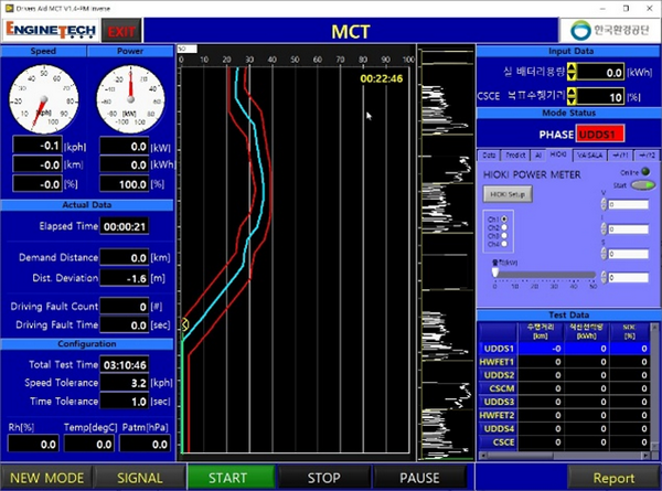
MCT Mode Driver Assistance System
Driver's Aid for MCT
- Patent No.: 10-2847287 Electric Vehicle Full-Charge Driving Range Evaluation System and Electric Vehicle Full-Charge Driving Range Evaluation Method
- This is Korea's first Driver's Aid program supporting MCT mode
- The driver only needs to input the battery capacity and the target CSCE ratio and then drive
- The software's predictive algorithm automatically adjusts the CSCM interval to ensure it reaches the CSCE target value
- Communication Features: Weather Station, Powermeter, Dyno
- The Test Then Report feature generates the final report after the test
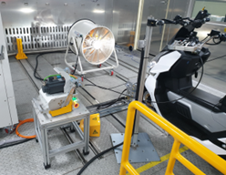
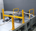
Automated Driving Robot
Autopilot
- Achieves both acceleration control and brake control with a single actuator
- Convenient Test Sample Position Calibration Function (LED LAMP Indicator when complete)
- Can be calibrated on-site immediately
- By controlling via wire type, it can also be used on four-wheel vehicles
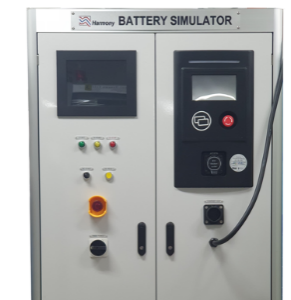
Battery Simulator
DC Power Emulator
- DC-DC Module: Siemens SINAMICS Series
- 4Q DC-DC built-in (bidirectional power supply)
- Touch screen user program
- Network: Apache Protocol Support
- Load-side relay built-in
Video Test Synchronization Device
Movie Sync
- Function to record driving status during testing
- Functionality to record in conjunction with the powertrain and DAQ DATA
- Display capability when linked with the powertrain and DAQ DATA
- Maximum compression by adjusting the frame rate

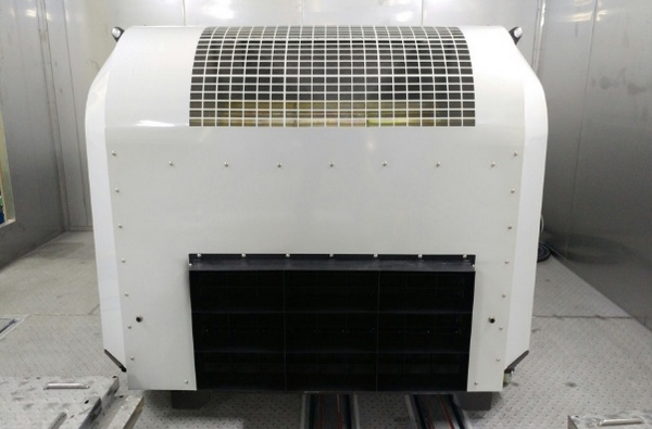
Blower
Cooling Fan
- Speed controlled proportional to vehicle speed up to 120km/h
- Flow rate, dimensions, and flow exit area comply with UNECE R83 regulation (EURO-5)
- Air velocity at blower outlet within ±5km/h of roller speed in the 10-50km/h range
- Above 50km/h, air velocity within ±10km/h of the corresponding roller speed
- Height from the lower edge above ground: 0.2m
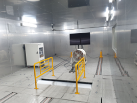
Environmental Chamber
Climate Chamber
- Temperature Control: Freezer, Heater
- Humidity Control: Dehumidifier, Humidifier
- Pressure Control (Operates during engine vehicle testing): Small Blower
- Pressure control unavailable during freezing: Engine vehicle testing is only possible at room temperature
- During refrigeration control, the dehumidifier minimizes air moisture content to reduce condensation
Applications
적용분야
Unmanned Robot Test
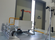
Mobile Cobot Test
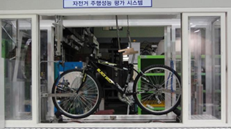
Electric Bicycle Test
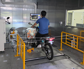
E-Motorcycle Test
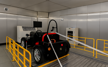
Micro EV Test
E-Quadricycle MCT Test
Engine Dynamometer
엔진 동력계
Integrated Testing Solution
We provide integrated testing solutions based on powerful networking solutions.
We are constantly developing to meet the diverse testing requirements of our customers, and we supply engine dynamometers specialized for engine testing, capable of both mode testing and transient testing.
The DNGV engine dynamometer maximizes user convenience to achieve Test Then Report.
Overview
제품개요
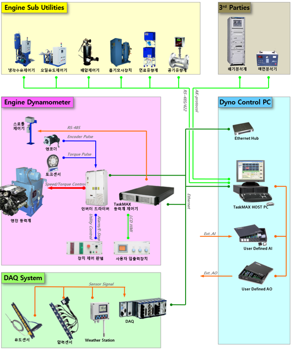
System Configuration Diagram
Features
주요특징
Specifications
주요사양
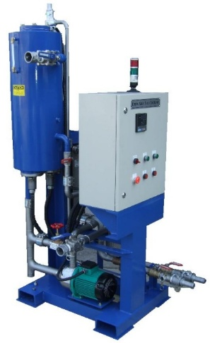
Fuel efficiency meter
Fuel Consumption Meter
- Coriolis force type flowmeter
- The Coriolis force measurement method enables real-time measurement of fuel quantity that changes according to engine conditions
- This measurement method enables real-time measurement of fuel flow rate, temperature, and density of consumed fuel
- Fuel conditioning device (optional)
- Built-in bubble detector enables precise fuel flow measurement even in the presence of air bubbles
- Precise temperature control is possible through heating/cooling control
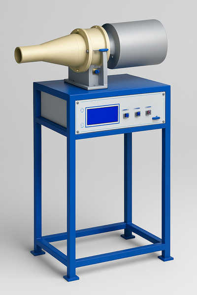
Air flow meter
Intake Air Flowmeter
- Engine Tech's air flowmeter uses Meriam's LFE (Laminar Flow Element), renowned for high precision and supplied to the U.S. EPA, ensuring high measurement reliability
- A wide range of options available to match engine capacity
- Equipped with a computer (optional) for real-time measurement data output and calibration
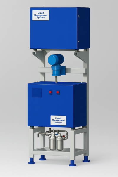
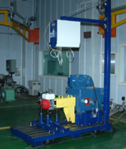
Engine Coolant Temperature Controller
Engine Water Temp Controller
- Precise engine coolant temperature control (engine inlet/outlet control)
- Heating and Cooling Output Control
- Alarm Indicator Light Installation
- Application of various safety devices
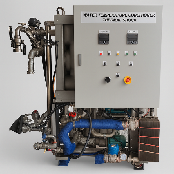
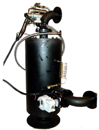
Engine Thermal Shock Tester
Thermal Shock Controller
- 0~110°C temperature control
- Compact size
- Fluid engineering tank design
- Pneumatic actuator heating/cooling switching
- Automation integrated management (communication control)
- Current status and control status display
- Manual/Auto control
- Application of various safety devices
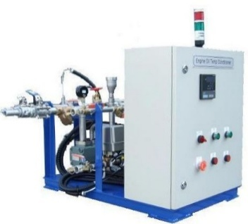
Engine Oil Temperature Controller
Engine Oil Temp Controller
- Precise engine oil temperature control (engine inlet/outlet control)
- Heating and Cooling Output Control
- Alarm Indicator Light Installation
- Application of various safety devices
Exhaust Back Pressure Control System
Engine Exhaust Back Pressure Controller
- Exhaust back pressure refers to the stagnant pressure in the exhaust system caused by resistance from the exhaust pipe, muffler, and catalytic converter
- Exhaust back pressure increases as engine speed and load increase, causing a decrease in power output and fuel efficiency
- The EGR system reduces the concentration of nitrogen oxides in exhaust gas and has the effect of lowering combustion temperature
- The valve is located in the intake manifold and controls the opening of a small passage between the exhaust pipe and intake pipe
- Certain types of EGR valves are opened by negative pressure, and a certain amount of exhaust back pressure is required to open the valve with this negative pressure
- The exhaust back pressure control system enables monitoring and control of exhaust back pressure during engine testing
- Exhaust back pressure can be a variable in engine performance and should be considered in engine development
Applications
적용분야
Altitude Simulation Dyno
Agricultural Engine Dyno

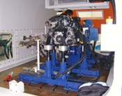
DNGV Engine Dyno (14 Units)
Motor Dynamometer
모터 동력계
Integrated Testing Solution
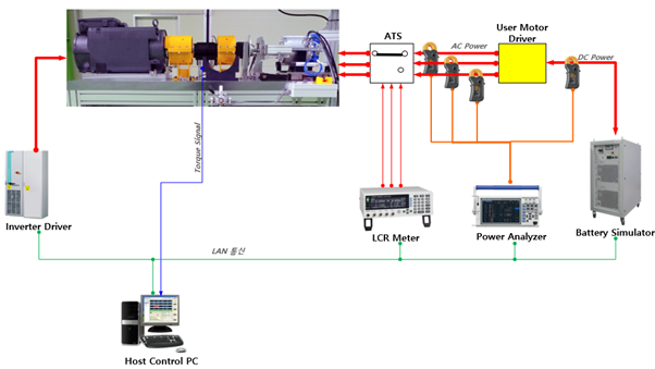
We provide integrated test solutions based on powerful networking capabilities. We continuously develop to meet diverse customer testing requirements, specializing in motor testing by supplying motor dynamometers capable of motor performance and endurance testing. The key feature of DNB motor dynamometers is maximizing user convenience to achieve Test Then Report.
Overview
제품개요
System Configuration Diagram
Applications
적용분야
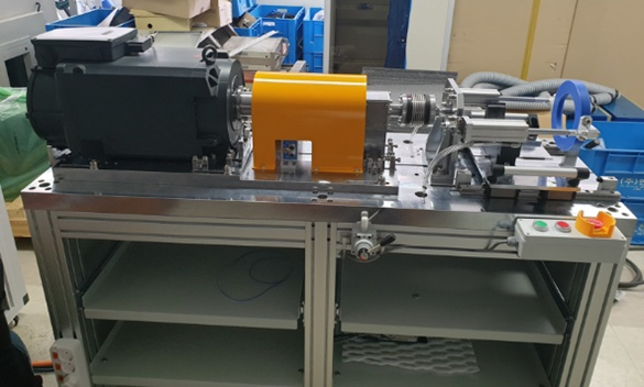
30kW Motor Dynamometer

34kW, 110kW Motor Dynamometer
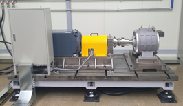
150kW Motor Dynamometer


